Mitel 3300 ARS Programming

ARS on the Mitel 3300, Mitel MCD and MiVoice Business platform is almost totally necessary for the system to route calls out trunks, but by default it is not set up and is not the least bit intuitive. If you use the Mitel Integrated Configuration Wizard to set up a new system it will configure the ARS for you, but what did it do? If you needed to add or change it, would you understand it?

This post is intended to give you a solid foundation for understanding, planning, programming and troubleshooting ARS. It is not a step by step manual on programming everything. I omit programming trunks, class of service setup, and probably a hundred other things.

Mitel ARS Worksheet
Mitel ARS Worksheet

Decide What You Need

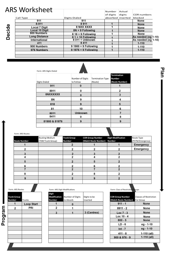
You can see the picture above is the ARS worksheet they hand out during Mitel training. It is very handy if you need to set up ARS from scratch or need to modify an ARS that you didn’t program.

At the top our first step is to decide what needs to be set up. In my example I outline a “normal” North American numbering plan for a single Mitel system. I went though all the regular numbers someone might dial and planned out how they will work. I named each route as this makes it so much easier to change or troubleshoot later. Mitel has no good way to name routes or plans in the system so if you have this worksheet to refer to and change, you will be much better off.

The list of possible numbers to be dialed are outlined as well as the leading digit. On many Mitel systems you need to dial 8 to get an outside line, so we will need to set up the Digit Modification Plans to strip them off. Note that some system use 9 for outside calls, and some may even use 6 or 7.

For our first, most important entry, 911 (US emergency services call), we have essentially 2 entries, 911 and 8 911. This is required in the US under Kari’s law. If someone were to be in a rush and just dial 911 without the 8 the call must go out. So there is an entry for 911 that strips (absorbs) no digits, and one that strips the 8 off the 911.

The last column is for setting up COR, which is the Class of Restriction. COR on Mitel is another hard thing to understand. It was explained during training as “If you are in, you are out.”, meaning if your extension’s COR is listed in the COR group, you can’t make the call. Lets say for example you need the lobby phones to be blocked from making 10 digit local and long distance calls. You could decide to set the COR number for that phone to 10. Now you assign that 10 to the COR Group matching the local 10 and long distance routes you set up (bottom right of the pyramid). Now when that extension makes a call that goes out that route, the system looks at the route’s COR Group and sees it has 10 in it, and because the extension’s COR is in… it is out!

Plan

Down the right of the worksheet you can see the arrow goes down, indicating you plan and fill out this sheet from the top down. If you set up the deciding phase at the top completely, filling most of the rest out is straight forward.

Starting at the top you break down the digits dialed, which you already did above, but this time with the addition of how exactly you will program it.

The top form on the pyramid is ARS Digits Dialed, and each column is a field you will have to program. There are many ways you can set up your digits dialed, up to and including having the entire actual number in the digits dialed, rather than wildcards. I have the Termination Type blank because for the example they will all be set to Route.

The final column is the Termination Number (Route Number). It is very important for being able to understand the ARS to stick to using different route numbers for separate rules and using the same number for routes and COR groups per rule. For example, if the route number for long distance matches the COR group and you have it all written down (on your handy worksheet!) blocking someone from making long distance calls is a snap. If the route and COR group numbers don’t match for a rule and you don’t have the rule defined on paper, blocking calls takes much more digging, as does any other changes or troubleshooting.

The next step down the pyramid is the form ARS Routes. Here we enter the routes we programmed above and decide how to send them out the system. I have left Routing Medium blank, again because we will just use TDM Trunk Group for all of them.

Next over is the Trunk Group Number, which I decided to use 2 as we will set that up for the PRI trunk group when programming. After that is COR Group Number, and remember what I said earlier about making sure to match the route number and the COR group number to make it easier later.

In the Digit Modification Number column I’m using 1 and 2 for this worksheet. The digit mod 1 plan will not absorb any digits for our 911 calls, and digit mod 2 will absorb one digit, which takes the 8 off the outgoing calls. If you needed a plan to insert a number for calls going out old Centrex lines, this would be where you could set up the digit mod plan and assign it to the route (for example the digit mode plan 3 I have set up below).

At the far right our two emergency routes are programmed as Route Type – Emergency. This is so when the 911 or 8911 numbers (or any number you decide is an emergency call) are dialed it can ring a group of phones to let them know the emergency number was dialed. The emergency group should be set up prior to programming your routes and before testing emergency calls, but I’m not going into that here.

For the bottom of the pyramid we decide what trunks we are going to program, the digit modification plans, and the class of restrictions. I have more trunk groups programmed than we are using in this example, as well as an third digit modification plan, just so you can see some additional options.

At the bottom right we see the Class of Restrictions for Groups where everything comes together. If we put the name of the rule with the route number and what group we plan to restrict from using that rule in here correctly, making changes later is simple. Someone can’t make international calls? Well we set up international rule to go out route 7 and use COR Group 7, so do they have a COR number between 1 and 10? If so, change their COR on their extension to something outside of 1-10 and they are no longer restricted!

Program

With all of the planing done on paper we can start programming the actual system. We program from the bottom up as each layer builds on the other. Again remember that I’m omitting quite a bit here assuming you can program a trunk group, set the COR number on an extension, etc.

Mitel 3300 PRI Programming

This post might be niche, but it took me a while to get it working so I thought I would document it here. If you have a Mitel 3300, Mitel MCD or MiVoice Business system with a digital circuit license and a T1 card, you can set it up to be the “phone company”. This way you can connect the system to other phone systems via T1/PRI and pass calls between them. I use it for testing, but it could be for production system also. Most of these settings will work to connect the system to the phone company in the US with standard T1/PRI options. I have tried to note where the settings deviate.

You will see in the pictures that I was using a rather old Mitel MX system. This setup will also work for newer hardware and software, it will just look different. The places where you make the changes in the newer systems will be different, but all of these settings are in the newer systems… somewhere.

Framer Configuration

First set up the card itself. Go to the port you plan on using and change it to T1 interface type.

Mitel Framer Configuration

Link Descriptor Assignment

Under Link Descriptor Assignment use the settings below. Please remember these settings are specifically for connecting to other phone systems, not the phone company. These settings seem to be the same to connecting to the phone company, with the exception being the Address for Message Control will be set to “B”. Also note that under Termination Mode I have it set to NT for Network Termination. With this termination mode I had to use a T1 crossover cable to link to the other phone systems T1/PRI card and get the signals synced.

Mitel Link Descriptor Assignment

Digital Link Assignment

Program the Digital Link Assignment next.

Mitel Digital Link Assignment

MSDN Trunk Circuit Descriptor

What do all those letters mean? I always have to look them up but all you need to do is set this page up like so:

Mitel MSDN Trunk Circuit Descriptor

Trunk Service Assignment

Here we assign the Class Of Service to the trunks. Note that I skipped creating a COS for the trunks. There are a few specific settings in the COS you need to change to use the trunks. In this example I have COS 21 set up for the trunks. Here are options that you usually need to set to yes:

ANI/DNIS/ISDN Number Delivery Trunk, DASS II OLI/TLI Provided, Public Network Access Via DPNSS, Public Trunk, Display ANI/DNIS/ISDN Calling/Called Number, Display ANI/ISDN Calling Number Only, SMDR External, SMDR Internal

For any phones actually using the trunks you need these options set to yes for the COS they are assigned to:

Display ANI/ISDN Calling Number Only, Display ANI/DNIS/ISDN Calling/Called Number, and under the trunks section – DASS II OLI/TLI Provided, Public Network Access Via DPNSS

When you fill out the Non-dial In Trunks Answer Points make note that I put in the voicemail number for this system. That way when I call I get the VM and can go from there. If you want to you can put in an extension. You could also just send the digits received as is by leaving the Non-dial In Trunks fields empty and put a 0 in the Dial In Trunks Absorb field. With that setting you can dial the extensions you want to ring directly from the other phone system. You can also set up system speed calls matching the incoming digits to go to extensions, hunt groups, or whatever. Also in newer systems you can tick a box for DID and then put the incoming digits being received in the DID form and point them wherever you want. The options are endless!

Mitel Trunk Service Assignment

Digital Trunk Assignment

Now we configure each of the 23 trunks (if we are setting up a PRI). You just need to go to the first circuit and put 23 in the number of records you want to change. Then set the trunk number to something like 100 and increment by 1. Set the Trunk Service Number to the Trunk Service Assignment you just set (choose “Change all to”). Set the Circuit Descriptor Number to the number you assigned to the Link Descriptor at the start. Why do they call it something different here? A mystery for the ages. Set the Interconnect and Tenant to 1 for all trunks unless you have a good reason not to.

Mitel Digital Trunk Assignment

Network Synchronization

Program this page to point to the card and slot you programmed at the beginning. If you don’t know what numbers to use, look at the first trunk listed above – 6, 1, 2, 1 in this example. That is what you enter for your clock source. Mitel docs state that if the system is the master this should be blank, but it worked fine filled in when I was testing.

Mitel Network Synchronization

T1 Protocol Assignment

Nearing the end of the programming we set the protocol we intend to use. Once again, this contains settings that will not work if you are connecting to the phone company whose equipment will be the “master”. Here you are setting the Mitel up as the master to the other system you connect to. If you were connecting to the phone company, then the master field would be left at the default false.

T1 Protocol Assignment

Trunk Group Assignment

Here is a little trick about creating the trunk group in a Mitel 3300 system. If you enter the settings below, assuming you created trunks 100-122, when the system adds the trunks it will add them in reverse. You want to do this in most cases so when you make outgoing calls the last trunk is chosen first. Most of the time calls come in on the first trunk and go up, so it is a good practice to have the calls go out on the last trunk and go down from there.

Mitel Trunk Group Members

See below for what you should end up with after programming the trunk group.

Mitel Trunk Group Assignment

Now you should be able to connect your T1 crossover to another phone system and program that system as if it is connecting to the phone company. You still have to set up ARS to make outgoing calls, so maybe I’ll cover that in another post.

Mitel SX-50 Programming Mode

In this tutorial I will cover how to place a Mitel SX-50 into programming mode. Note that this info carries no warranty and all risk is assumed by the user. In other words if you don’t know what you are doing something breaking is not my fault.

Putting the SX-50 into read/write mode

Step one is to remove the front panel of the system. Usually you have to turn the key on the very bottom of the system cover to unlock the latch. Then you can pull the bottom away from the wall and lift the front panel up off the chassis. On the right side of the chassis you will see a series of dip switches, usually in a red case. Switch one needs switched to off to put the system into read/write mode before programming, and should be put back to on when programming is done to prevent accidental programming.

Once that is done go to the console phone, hold the Status button and dial 7772 while holding status. The SX-50 on the display should flash indicating the system password for programming is correct.

Finally dial 70 on the front console and the display should show “Enter Command”. This is where you put in your command numbers to access the customer data entry registers. It gets very complicated from here and if you don’t have a command list as well as a circuit ID list you certainly can’t “poke around” and figure it out.

When done press the release key on the console or press the exit softkey. Then return switch one to the on position and put the front cover back on the SX-50.

Mitel SX-200 Dial In Trunks Explained

In this post I will explain some of the fields in a Mitel SX-200 system form 15, which is used to configure dial in trunks (for T1 and PRI circuits).

Mitel SX200 Dial In Trunks

In CDE form 15 you will see the settings for dial in trunks which receive digits from the carrier. These circuits can be T1 or T1/PRI.

N – This sets the number of digits received from the carrier. In this case 4 digits are being sent to the Mitel.

M – This is the modify setting. Zero means it is not modifying the received digits, but for instance a three in this field would mean strip the first three digits. This could be used if the carrier was sending 7 digits but you only needed the last 4.

X – The X field is for inserting digits. Here you can see a 6 is being added to the received digits. A common number to see here would be 34, which usually matches a feature code for the Digit Translation Table form. You would need to check the feature code form to verify this, and if the X number matches that feature code then you check form 55, the Digit Translation Table form to see where the received digits are being sent.

CDN – Finally this is the circuit descriptor number. The settings for the circuit are set in that form and assigned here.

Mitel SX-200 Voicemail Password Change

Mitel SX-200
Mitel phone system

This process works for embedded voicemail on Mitel SX-200 and should also work on older version 3300 systems.

If you have a hotel phone system answered with an auto attendant you can be at very high risk of having your voicemail hacked. This is due to the fact that Mitel hotel systems are very popular and that security on them was very poor when they were produced way back when. Hackers have a list of hotel numbers and when they call them and get voicemail they will immediately try to access the voicemail admin. When they do they will attempt to use the technicians password, which is quite often left at the default. No, I will not put that password here, sorry.

To change the admin and manager voicemail passwords you can use the serial connection to the system and go into the proper form. The problem is most techs don’t know about the technician password which has to be changed from the TUI (telephone user interface). This is done by dialing the voicemail hunt group from a phone, or by pressing the voicemail key on a phone. The steps for making that change follow.

Technicians voicemail password change procedure

Pick up the phone handset and dial voicemail. When the system asks for a password press the * key to log into a different mailbox. When it asks for the mailbox input the admin mailbox number, which is usually 999 or 9999. Then the system will ask for a password. This is where you put in the technicians password. This provides access to the hidden option to change that password. The hidden option is reached by pressing 9. If you are logged in under the technician account you will hear “Please enter a technician function code”. The code for changing the password is 17271, so input that. Once you dial that you should hear “Please enter a technician function code” again, but this time you put in the digits of the new password. Remember to keep the length the same as the old password. When the new password has been entered the system will say “Please enter a technician function code” one last time and this time you put in the new password again to verify it (you do not want to get this password wrong!). If you verify the password the system will say “Your passcode has been changed”. Now you can hang up the call.

Capture system programming on a Mitel SX-200 ICP

This is for Mitel systems with network ports only. Digital systems are out of luck.

Serial connection into system

Form 11 Data Circuit Descriptor – supposed to be for setting speed – default works fine, usually no changes needed

Form 12 Data Assignment – pick a PLID and set an extension and SOCKET type– on old systems the port is defined by the PLID like 6 13 25 would be telnet port 61325 or on newer system the port is 613XX where XX is the last two of the port, ignoring the rest of the PLID. The last two of the port will always be from 20-28.

Form 34 Directed IO delete the CDE to printer and make a new entry for port 613XX (or set the device type for the extension you just set up) for CDE Data. You can also make a new entry for CDE DATA instead of deleting the printer if you have an open spot available in which case the extension defined in form 12 defines the telnet port, as shown above.

Open Putty telnet port 613XX (20-28)

From serial connection form 32 select form to print and alt-8 to print. You will see it on the telent session. Copy clipboard of telent session to notepad or other Word type program.