For this post we will go over the simple process of programming music on hold for an NEC SL2100. We will use PCPro EasyEdit as well as the System Data tab. This will require wiring and an external music source if you plan on using something like an MP3 player or radio.
Assign MOH Port in Chassis View
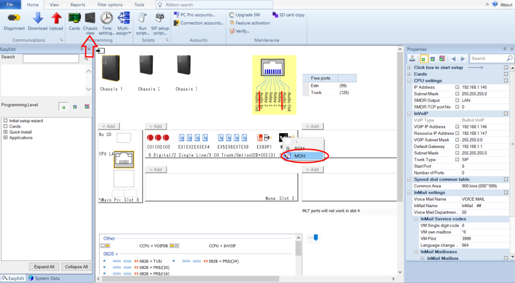
Once connected to the system with the full system data downloaded click the Chassis View button near the top of PCPro (see picture below). From there on one of your digital station cards right click an unassigned spot in Slot 1 and select MOH. You can sort of see in this example the other port has been assigned to external paging. When you have the Slot 1 area highlighted you will see a pop out for the wiring above. I highlighted the Audio In portion where you will need to wire your external device to unless you just plan on having tone sounds.
NEC SL2100 Music On Hold Setup Step 1
Music On Hold Setup
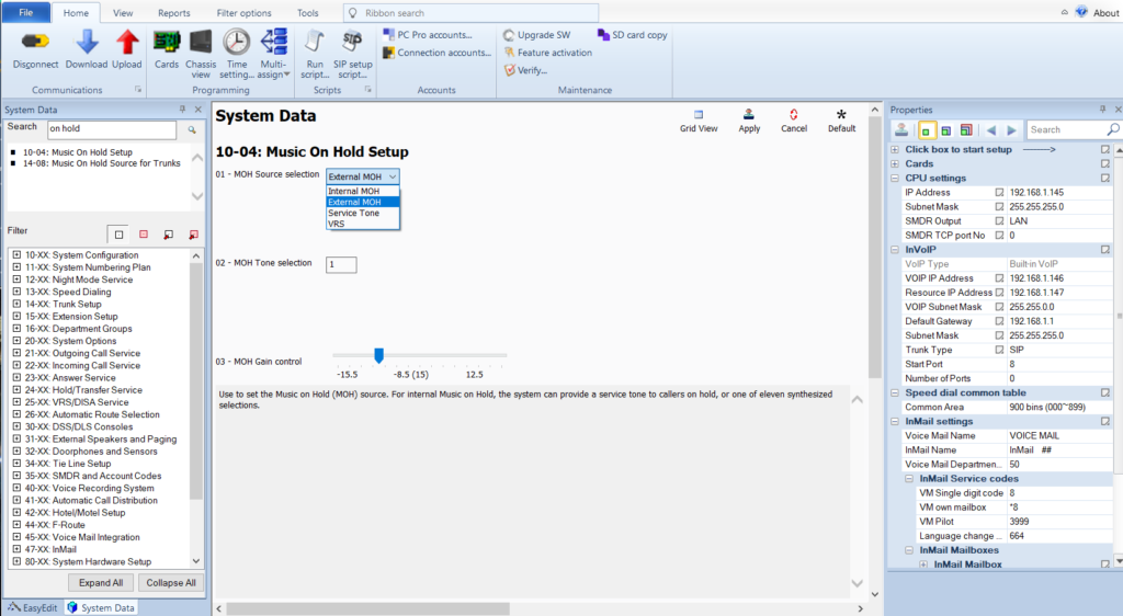
Next go to the System Data tab on the lower left corner of PCPro and navigate to form 10-04. Here is where you select what type of music will play when a call is placed on hold. Above we set up the physical connection for external music, so here we are choosing that from the drop down. You can also select internal music, external, service tone (just a beeping sound) or the voice response system.
NEC SL2100 Music On Hold Setup 2
Check MOH Assignment for Trunks
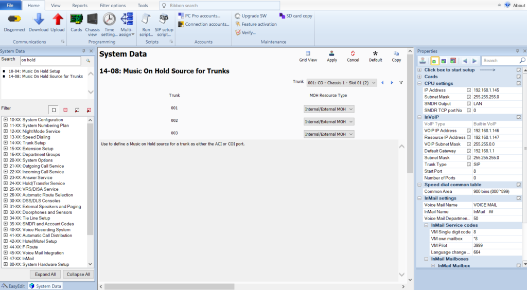
Last step is to go to form 14-08 and make sure it is set correctly. It should be defaulted to Internal/External MOH, which is what we want. Now upload all changes to the system. If you have a music source connected you should call in and put the call on hold. You can change the volume to suit the music, but in my experience the music will just not sound good. The system is not engineered with high quality music in mind. Remember that you don’t want customer’s hearing the music that much anyway.
When it comes to phone lines many companies consider SIP trunks due to their reduced cost and flexibility. You can usually get a SIP trunk for less than a traditional phone line and they are not tied to your current location. If you needed to move offices, you just move to one with an internet connection and the SIP trunk “follows” you. A traditional phone line would require your carrier to schedule and physically move the wiring.
NEC SL2100 systems come with 8 VoIP channels by default, which can be used for IP phones, SIP trunks or a mix. You do however have to buy additional licenses for the SIP trunks, so take that into consideration. They don’t cost much per channel (think of a channel like one phone line), so buying two or three won’t break the bank. Update – as of SL2100 firmware version 4 you can use up to 16 built in VoIP ports without a daughter board – requires licensing for additional 8 ports.
Licensing for SIP Trunks
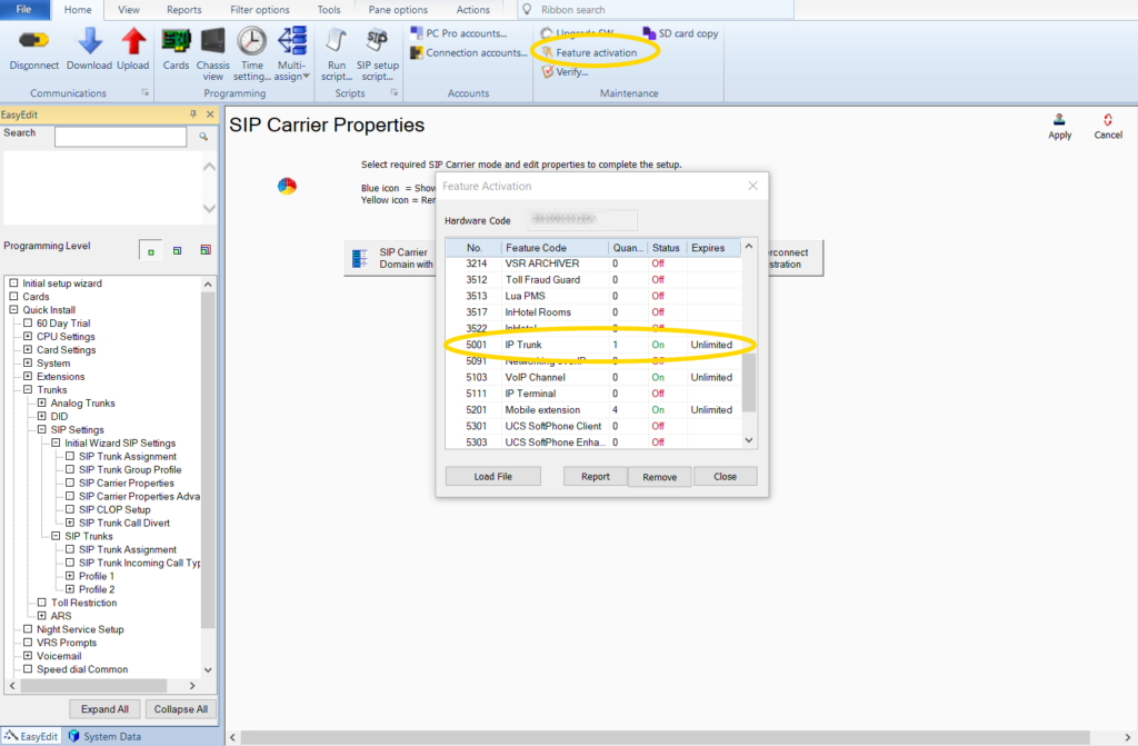
First you need to buy one or more IP Trunk licenses. You can find them sold online from reputable dealers, you just need to provide your hardware code and order license SKU BE116745. In the picture below after connecting to the system I clicked Feature Activation and scrolled down to see how many I have (I have installed one). If you order one the provider will email you a new license file in a few hours or the next day. Once you have that file you come back to Feature Activation and choose Load File and upload that new license.
NEC SL2100 Feature Activation
Configure System and SIP Trunk Properties
The next section is actually two parts. I’m skipping the majority of configuring the system, because I covered it in setting up IP phones. This all assumes you are using a base system without a VoIP daughter card, so if you follow setting up your System IP, VoIP IP Address, Resource IP Address and Default Gateway in the link above you will be set. Note that if you make changes to any of those IPs a system reset is required after you upload the changes!
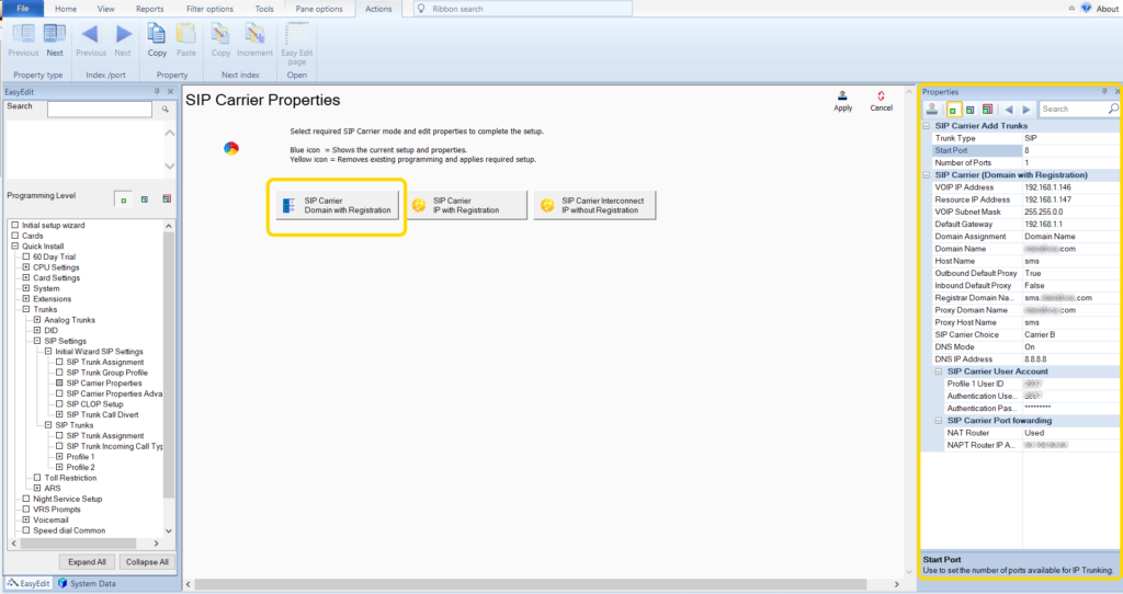
Select Easy Edit by clicking the EasyEdit button on the lower left side of the screen and expanding Quick Install, Trunks, SIP Settings, Initial Wizard SIP Settings and highlighting SIP Carrier Properties. In this example I am using SIP Carrier Domain with Registration, which I think would be the most common setup. When you click the button SIP Carrier Domain with Registration it configures the system and fills in some data for you. If you click any of the other SIP Carrier buttons in the middle of the screen the system will change some of that data, so be careful what you click!
Once your system is primed for Domain with Registration you can fill in the properties shown on the right of the screen. Check out the picture below:
NEC SL2100 SIP Carrier Setup
Remember in a base system you have 8 built in IP ports, and in this example I’m starting at port 8 and only using that one port. If you had three SIP trunks (and licenses for them) you could put the start port as 6 and number of ports to 3. Fill in the rest of the SIP carrier information that you should get from the carrier. It is also a good idea to set up the SIP Carrier Port Forwarding if you are behind a NAT router, which almost everyone would be. In the NAPT Router IP you would put your outside IP address. Be sure to apply and upload any changes made.
Once this is done check with your provider, either by calling them or logging into a customer portal to see if your system is connected and registered. If it isn’t try and see if the provider is even seeing your system. Maybe the user ID or password was incorrect. It may require a reset of the system to get it to start talking to the provider also.
Configure SIP Trunk DID
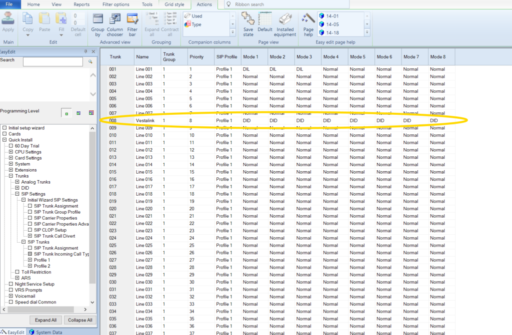
Now that you have trunks registered you need to assign the trunk type as DID for all modes. In Easy Edit you can expand SIP Trunks and then highlight SIP Trunk Incoming Call Type. Set the trunk (in my case I set it as 8 above) to DID for all modes.
NEC SL2100 SIP Trunk DID Mode
With that done and uploaded you can assign the DID to ring in to the target. DID means direct inward dial and it is the number “tagged” onto the incoming call so you can route it in your system. In Easy Edit expand Quick Install, Trunks, DID, and highlight DID Routing Tables. Because we assigned it to DID above the trunk will use the table matching the mode, which for default systems means mode 1 will use table entry 0001 – 0100 and in mode 2 it will use 0101 – 0200. So for DID 0001 we put our received number, which is usually 4 digits, set a descriptive name for the DID and set the target to the number we want to ring. For the target we could assign an extension, or a virtual that goes to an auto attendant. Then for night mode go to DID Table Entry 0101 and set it up like you just did, but maybe in night mode you want the target to be a different location.
In a previous post I went over manual day/night mode switching on an SL2100 and in this one I’ll cover the automatic option. Automatic switching is great for locations with well defined hours. If you are in and out of the office at the same time every day, auto mode is for you. You can also easily configure the holiday schedule with auto mode.
Prior to setting any of this up you need to plan on what you want to do. Most businesses are fine with two modes, day and night. Also most of the time two patterns are good enough, but maybe you have different hours on Saturday or Sunday and need three of four patterns. Have a list of your holidays on hand so they can be set up. Think through what you need and making your changes will be much easier.
Enable Automatic Night Mode Switching
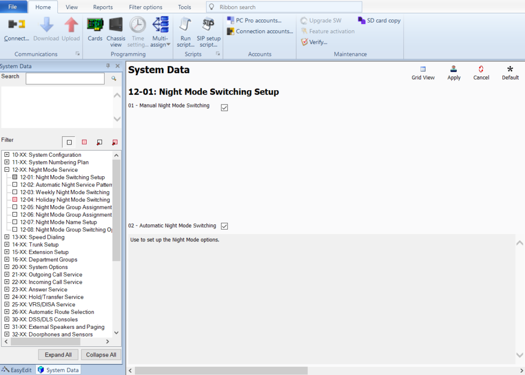
Step one after logging in to your system and downloading all the data is to go to 12-01 in System Data and putting a check mark in section 02. In the picture below you can see I have both manual and automatic checked. You can do this if for instance you need to leave the office early sometimes. With manual mode set up with day and night buttons on the phone pressing the night button will override the auto mode until the next scheduled time change. So if your normal hours are 8 to 5 and you need to leave at 4:30, pressing the manual night mode key will put you in night mode until the schedule takes back over at 5. Then it goes back to following the auto schedule.
Don’t forget after changes to hit the apply stamp near the top right corner of the screen and to upload all changes made when done! Otherwise all changes will be lost.
NEC SL2100 Night Mode Switching Setup
Configure Trunks for Different Modes
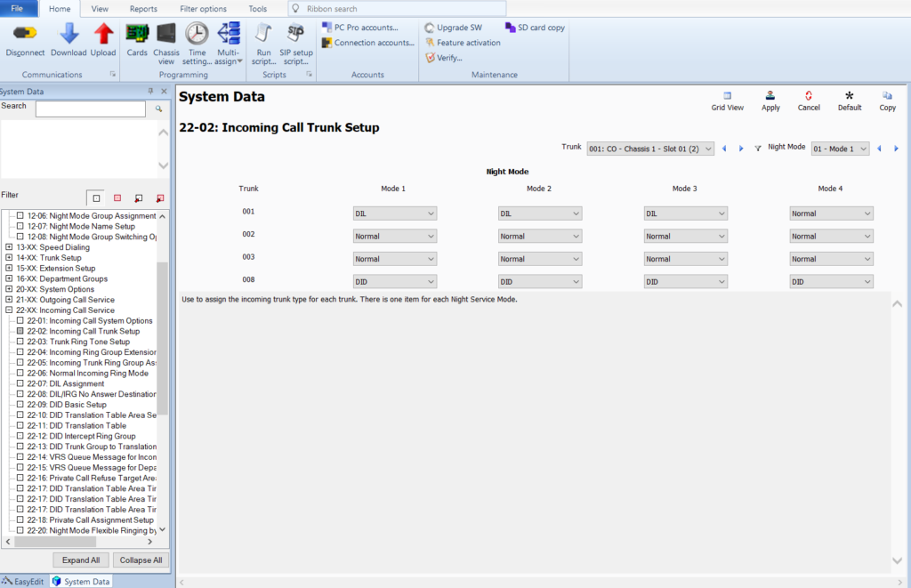
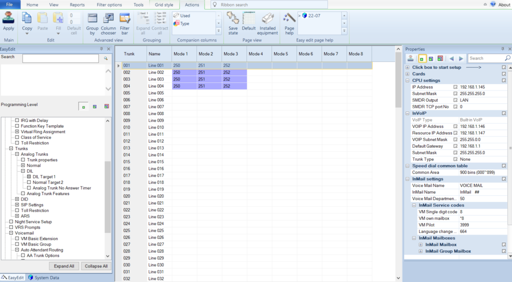
Second step I suggest is setting your trunks to do what you want when in your different programmed modes. In the picture below you can see I’m using trunk 001 for DIL in modes 1-3 and trunk 008 (a SIP trunk) as a DID in all modes. It is also possible to have your trunks go to the Normal location (like to a ring group) instead of DIL, it all depends on what you want. In my case the trunk rings a DIL because it goes to an auto attendant with a greeting and call routing. The SIP trunk goes to a DID Translation Table where mode 1 goes to one location and mode 2 goes to a different one (the same auto attendant I set up for the regular trunk).
NEC SL2100 Incoming Call Trunk Setup
Trunk Mode Assignment Example
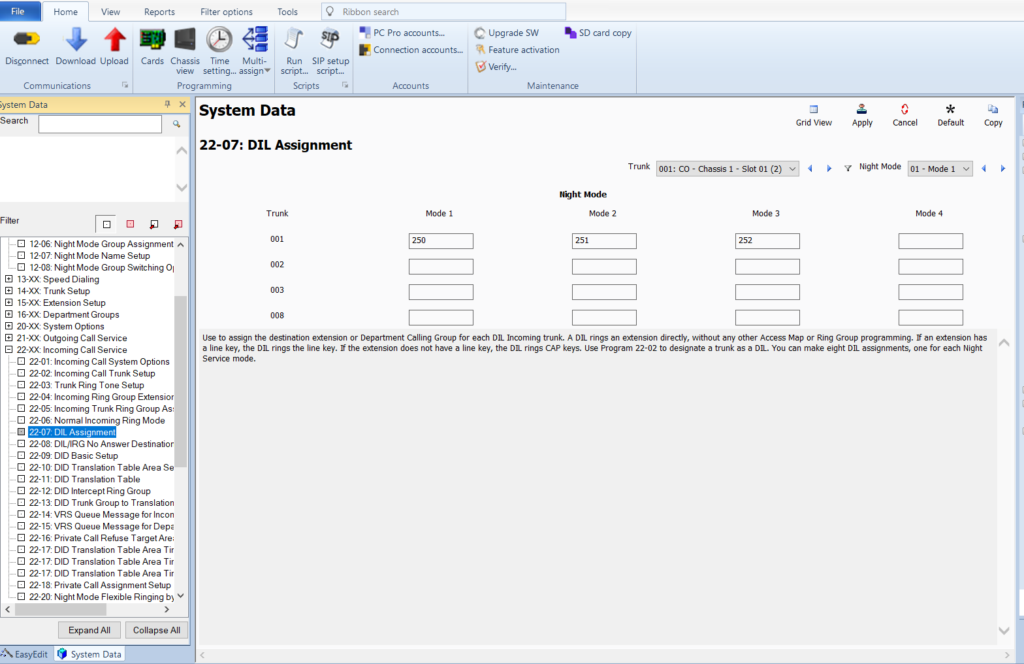
Below is a picture of how I have the DIL Assignment set up for trunk 1, shown above. You will see three modes here while in this example I’m only using two. The third mode is for “special holidays” like if the office was closed for a special occasion. For now ignore it. This is just an example to show where the modes we are about to set up will go when we complete the final step.
NEC SL2100 Trunk Mode Assignment
Schedule and Pattern Configuration
For the final step we turn to our old friend Easy Edit. In the lower left of the screen click the EasyEdit button then expand Quick Install and highlight Night Service Setup.
The display you get can be confusing until you know what each part does, which I will attempt to explain. Adding to the confusion is that every night mode is shown, when most people will only use two or three. Flexibility I guess?
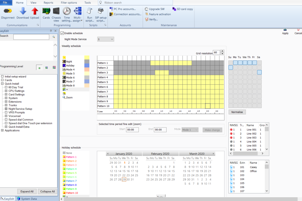
NEC SL2100 Night Service Setup
In the picture above the top left hand side has our different modes. Mode 1 has the sun icon with a yellow box that will show when assigned to the pattern. Remember above where we set mode 1 for the trunk to DIL to an auto attendant? Night mode is a grey box. For this example the office is setup with pattern 1 for Monday through Friday from 8 to 17:00 (5pm). Pattern 2 is completely grey, so you know it is all night mode. Pattern 3 is set up for Saturday so the system is in night mode for all hours except 9 to 12 where it follows day mode.
Look to the right of the colored boxes to see where I assigned the days to the patterns. Monday through Friday are highlighted next to pattern 1, and so they will follow that pattern. Sunday is highlighted next to pattern 2, which is all grey for night mode because the office is closed all day Sunday. If you needed to also be open for Sunday from 9 to 12 you could click the box for Sunday just to the right of pattern 3, just like Saturday. Or if you needed different hours for Sunday you could make a new pattern and assign it.
Below the patterns is the holiday schedule. A simple explanation would be that you create the pattern above and assign it to the holiday below. For January 1st 2020 you see the day is orange, which corresponds to pattern 2 shown just left of the calendar. So when the day matches the system will override the day schedule and follow the holiday schedule, which for pattern 2 is night for the entire 24 hours. Probably you now see the flexibility for holidays, like if you needed to be closed at noon on New Years Eve. You could make that schedule in pattern 10 for example, then assign pattern 10 below to New Years Eve.
Last thing to mention about automatic switching is it is entirely dependent on the system time and date being correct. The common issue is that someone sets all this up and it doesn’t behave like they expect because they don’t have the correct time or date on the system. Luckily most NEC phones show the time and date on the display, so it can be a hard mistake to miss. But check it to make sure, and probably just set up NTP so you don’t have to worry about it being wrong.
Setting up a company directory is a great way to increase your customer satisfaction by making employees easier to reach. It also frees up a person who would otherwise need to take the call, find out who the caller wanted to speak to, then transfer them. In this post I will explain setting up the InMail on an SL2100 for the directory feature. This should also apply to the SV8100 and SV9100 if they are using the integrated voicemail.
Configure a Group Mailbox
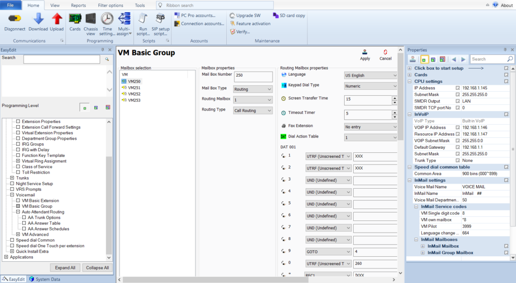
First we are going to set up a group mailbox as routing and change the mailbox number to something other than 1. I’m using EasyEdit as always. Expand VM Advanced and select VM Group Setup. In a default system you probably already have lots of group mailboxes, probably starting with 31XX. You can use those if you choose. In my picture I cleaned those out and used my own extensions, some matching virtual extensions that I programmed for day/night routing. I’m using group mailbox 4 and I added a number to it and set the routing mailbox to 4.
Be sure to apply settings after you change them and upload the config to the SL2100 when done! Otherwise the changes don’t go to the system.
SL2100 Group Mailbox Setup
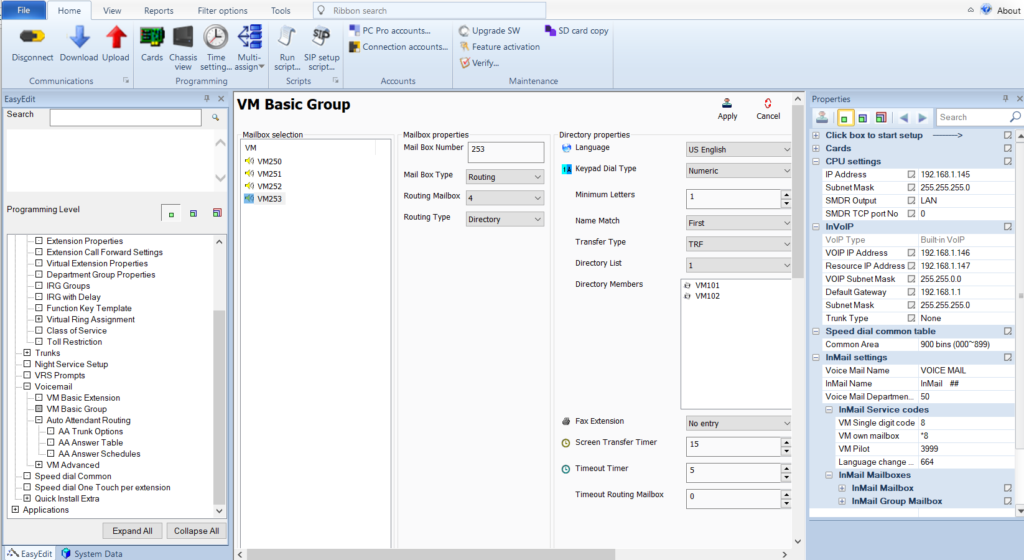
VM Basic Group Directory Setup
Now we configure the new group mailbox that is routing mailbox 4 as our directory. Under Voicemail, VM Basic Group select the new group mailbox you just defined. Set the Routing Type to Directory. On the right you can set the options for the directory like matching first or last name and number of letters to match. The important thing is to make sure your Directory List is set to 1 (or whatever number you choose to use). This is the number we will assign to the extensions we want in the directory. If you wonder what the Directory Members on this page are for, so do I. I couldn’t find what they were in any docs and I could not change them. Must not be important? – update – The Directory Members box fills up with the mailboxes you assign below. Once you assign the mailbox to the matching directory, in this case 1, it will auto fill this box so you can quickly check that the mailboxes you need are in the correct directory.
SL2100 VM Basic Group Setup
InMail Directory List Assignment
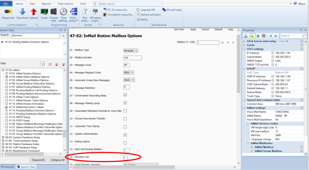
For each mailbox you need to make sure the Directory List you are using is assigned. This is done in System Data form 47-02-15. I couldn’t find it in EasyEdit. For every mailbox you are using make sure entry 15 matches the directory list you are using.
InMail Directory List Assignment
Extension Names
Lastly, setup the extension names. In form 47-01-16 the Name Format is configured. By default it is first name – last name but it can be reversed. Whatever it is make sure that is how you name the extensions under Extensions, Extension Properties in EasyEdit. Having the extension names not match the format will ensure the directory doesn’t work. If you have an extension that you don’t want in the directory, just make sure the Directory List you set up in the last step is set to zero.
By default there is already a greeting for the directory, but it can be recorded for a more personal touch. Log into voicemail from a mailbox with system admin rights and dial 72, then 4, then enter the routing mailbox number you set up earlier (in this example 004). Now you can have a more personal directory greeting and say if the caller should dial the first or last name.
In my next post I’ll explain setting up a Dial Action Table so you can configure a button in the auto attendant to route the call to the directory.
Setting up an NEC SL2100 to answer incoming calls with an auto attendant isn’t hard, but it does have a few steps. In this post I’ll show how to set up virtual extensions to direct incoming calls to customer defined auto attendants. There will be an attendant for day, for night and one for holidays in this example. This assumes a new system with System Data form 12-01 set up for Manual Night Mode Switching.
Set Up the Virtual Extensions
Like all good SL2100 instructions we start with the brilliant EasyEdit in the NEC SL2100 PCPro program. It combines forms in a logical fashion so you don’t have to poke through the System Data or dig around in a PDF.
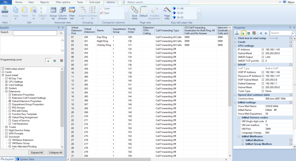
In EasyEdit expand Extensions then highlight Virtual Extension Properties. Assuming a default system you should have virtuals starting at 250. Name this Day Ring, 251 as Night Ring, and 252 as Holiday Ring. Then set Call Forwarding Type to Call Forward All Calls and in the remaining fields for call forwarding put in the voicemail pilot number. By default the VM pilot is 3999, but if not just look to the lower right on PCPro and it will show the pilot under InMail Service codes.
With all the steps outlined don’t forget to apply the changes in PCPro, then upload them when complete! PCPro does a good job of letting you know if you make changes that you did not apply, but not if you don’t upload them to the system when you are done.
NEC SL2100 Virtual Extension Properties
Set Up Routing Mailboxes for Virtual Extensions
Next we will add our new virtual extensions to the InMail as routing mailboxes. Where we always forwarded the virtuals to voicemail above this makes them our “Auto Attendant” mailboxes where we can record greetings as well as set where button presses go.
This next step is optional, but if you have a defaulted system and look at the picture below your VM Basic Group will not look like mine. I had deleted all the group mailboxes the 2100 has by default to make it “cleaner” and more clear what was in use. To delete the 31XX group mailboxes in EasyEdit, go to Voicemail, VM Advanced, VM Group Setup and in all those mailboxes just clear out the extension, then save and upload. This gives you a clean slate to work with.
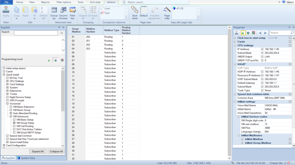
Once you have that done, or even if you don’t do it, it won’t hurt anything, go to Voicemail, VM Basic Group. It seems all group mailboxes defined like above just “appear” in the VM Basic Group form. For each new group mailbox set them to mailbox type routing, routing mailbox number 1 for 250 (Day), 2 for 251 (Night) and 3 for 252 (Holiday). Then set the routing type to call routing. Once that is done for each mailbox set the DAT (Dial Action Table) for 1, 2 or 3 to match the routing mailbox. This way each routing mailbox can have its own set of buttons to define.
I’m not going to go over setting up each dial action table, I’ll save that for another post. Also you may see I have a group mailbox 253 in this picture. It is for a company directory and you don’t need it for this example, but I’ll cover setting it up in a later post as well.
NEC SL2100 Routing Mailbox Setup
Recording Greetings for Routing Mailboxes
Before making these mailboxes live we should record the greetings for them. From a phone that has a VM admin mailbox (usually the first digital phone on a new system) make a call to voicemail and log into that extensions mailbox, then dial 72 to access the system admin menu. Once in the admin menu press 4 for instruction menu messages. Enter 001 for the day greeting, 002 for night and 003 for holiday and record your appropriate greeting. Don’t forget to save the recordings before you hang up!
Set Trunks to DIL Mode
Now we’re ready to point the incoming trunk calls to the new virtual routing mailboxes. First we set the trunks in use to DIL mode by going to Trunks, Analog Trunks, Trunk properties and changing all the modes on the trunks you are using to DIL instead of Normal (not pictured). After that go to Trunks, Analog Trunks, DIL, DIL Target 1 and set up the trunks that you are using like the picture below. Note that you may have more or less trunks in use, so this depends on how your system is actually configured.
NEC SL2100 DIL Trunks
Add Day, Night and Holiday Keys to Extensions
Finally we have calls ringing into our three modes so we just need a manual way to switch those modes. This can be done automatically, but for this example we will show how to do it manually.
Go to Extensions, Function Key Template and in the top left drop down select the extension you want to change the key on. On the left select the button 09 – Night Mode Switching and move the mode 1 button to a key on the phone. Then on the left side make sure it selects mode 2 (it does this automatically if you already placed a mode 1 key) and put that on the next key. Finally place the mode 3 button on a key. Apply and upload all changes you have made!
Now you can simply press the button for the appropriate mode and the system switches in a second. If the system is in any mode besides 1 (day mode) it will show on the display of the phone so it would be hard to get wrong. If you want to define the names of the modes you can go to System Data form 12-07 and program mode 2 as Night and mode 3 as Holiday so they show up correctly on the phone.
In this post I’ll go over the steps for programming Mobile Extensions on the NEC SL2100, which comes with 4 Mobile Extension licenses out of the box. The tutorial should also work for NEC SL1100 and for the most part the NEC SV8100 and SV9100
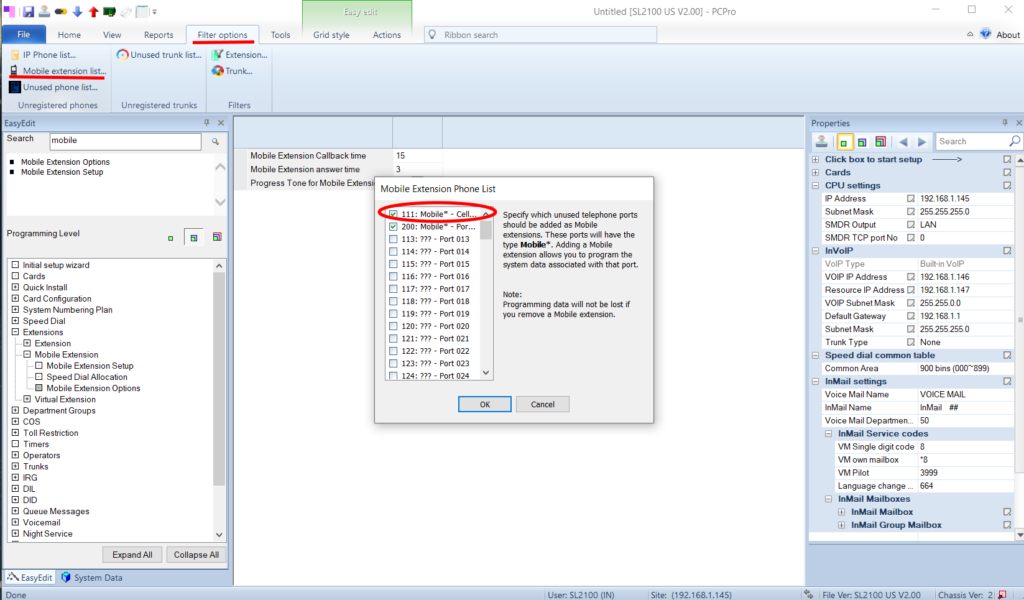
Mobile Extension Phone List
NEC SL2100 Mobile Extension Phone List
From the SL2100 PC Pro connect to your system and download the configuration. Then go to the Filter Options tab (see picture above), and click Mobile extension list to bring up the Mobile Extension Phone List popup. From here put a check mark next to an extension, click on the extension you want to assign and click okay. Don’t forget to apply changes and also to upload them when you are completely done, otherwise the changes are lost!
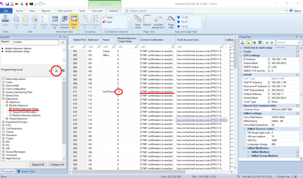
Easy Edit Mobile Extension Setup
NEC SL2100 Mobile Extension Setup
Next we are going to use the very handy Easy Edit tab on the PCPro program. Go to the Easy Edit tab in the lower left, choose the intermediate programming level (see the red circled area on the left), and expand Extensions, Mobile Extensions, then highlight Mobile Extension Setup.
Fill in the name field, and assign an unused Mobile Extension Target number (a system speed dial number). In a new system you can usually just pick any number between 1 and 899, but its a good idea to pick a high number and reserve those for your mobile numbers.
In the Connect Confirmation field you can see that the default is DTMF conformation is needed. This means when the call goes out to the remote phone, when they pick up they will hear a double beep. They will need to press the * button to actually answer the call. This keeps calls from ending up in the remote phones voicemail, which maybe you want, or maybe you don’t. You can turn off the DTMF confirmation, but if the remote user doesn’t pick up it will end up in their mailbox, not the one on the SL2100. It all depends on what you want to happen.
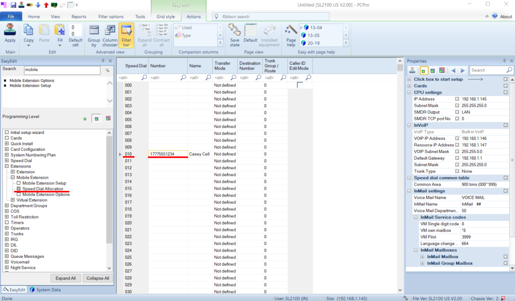
Speed Dial Allocation
NEC SL2100 Speed Dial Allocation for Mobile Extension
Now we fill in that Mobile Extension Target number, which is just a system speed dial bin. Click on Speed Dial Allocation just below Mobile Extension Setup, then go to the number you just assigned to the Mobile Extension and fill in the number and add a descriptive name. Be sure to use 1 if it is a long distance number from the phone system. You do not need to put in the trunk access code (8 or 9), the system does it for you.
Once you apply and upload these changes you should be able to dial the internal extension and have the call go out to the remote number. I suggest testing it now before we go on to twinning and call forwarding. If it doesn’t work check the number you just put it. Can you actually dial it from a phone (here you will need to put in the trunk access code)? If not, try changing the number until it works (remove the 1, add a 1, try just 7 digits, etc.). – edit – I just programmed a mobile extension and got reorder tones when dialing it until I rebooted the system, so if you get reorder tones try a reboot.
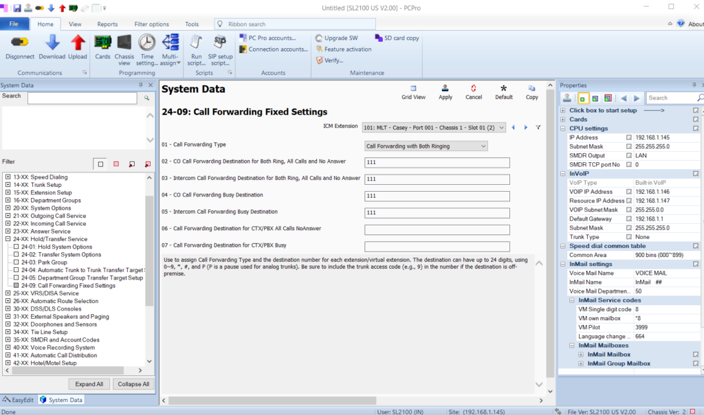
Twinning Desk Phones and Mobile Extensions
NEC SL2100 Twinning
From here we will go over “twinning” a desk phone and the mobile extension. Twinning is having two phones ring at the same time when one extension is called. So a call to your desk will also ring your mobile extension at the same time.
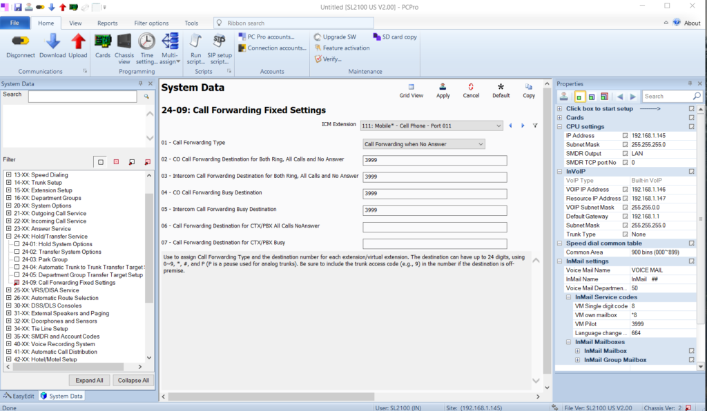
In PCPro change from the EasyEdit tab on the lower left to the System Data tab. Navigate to 24-09 for Call Forwarding Fixed Settings. In the ICM Extension drop down pick the desk extension you want to be the base number that is called. In the Call Forwarding Type field set it to Call Forwarding with Both Ringing, and in the next four fields put in the mobile extension you want to ring at the same time. Remember that when you twin the call like this unanswered calls will not go to the desk extensions voicemail anymore. You need to set up voicemail for the mobile extension, or just set it up so the call goes to the cell phone’s mailbox. This is best for customers who are out of the office more than in.
Mobile Extension Voicemail Forwarding
NEC SL2100 Mobile Extension Voicemail Forwarding
Lastly we can set to mobile extension call to forward to the phone system’s voicemail. You would do this if you set the DTMF conformation required to be on in step one. If the user doesn’t press *, when the timer runs out the phone system takes the call back and routes it to the voicemail box for the mobile extension. If you do not have DTMF conformation on, then don’t change this as the phone system will not have control of the call once it goes out to the mobile number and will end up in that mailbox instead.
In the System Data tab, go to form 24-09 and select the mobile extension from the ICM Extension drop down. Set the call forwarding type to Call Forward when No Answer and fill in the voicemail pilot number in the next four fields. In PCPro you should be able to see what the VM Pilot number is if you have the properties view set to on (View tab on the top bar, check mark next to Properties).
Apply and upload all of your changes. Be sure to set up the mailbox for this extension before testing it. You probably want to have this mailbox set up to send the message via email (voicemail to email license required).
Here is a list of default passwords for the NEC SL2100 phone system and where to find/change them. After an installation you should at the very least change the installer level password for the system to prevent unauthorized access.
SL2100 Administrator Passwords
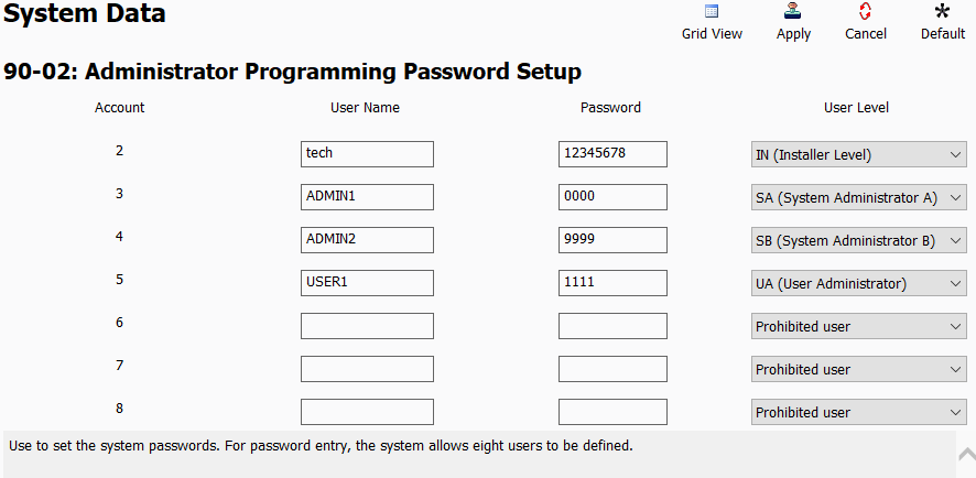
The admin passwords are in 90-02. Be sure to at least change the installer level password, and for added security change the username on the installer level user, and then clear out the remaining accounts unless you have a good reason to use them.
NEC SL2100 Default System Passwords
Programming Level Setup
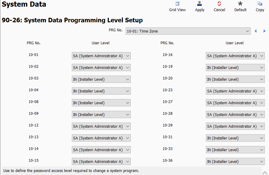
You can change what forms defined user levels have the ability to change from form 90-26. If you wanted a user administrator level user defined in form 90-02 to be able to change the time for instance, you can adjust it as well as any other form from here.
NEC SL2100 Programming Level Setup
User Programming Passwords
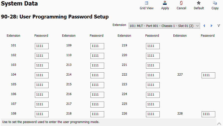
In form 90-28 you have the default passwords for the individual extensions user programming modes. These are used for the User Pro web access. It is a good practice to change these from the default for users that need to use this feature. If the extension doesn’t need the features, clear the password field out to totally prevent access from that extension.
NEC SL2100 User Programming Passwords
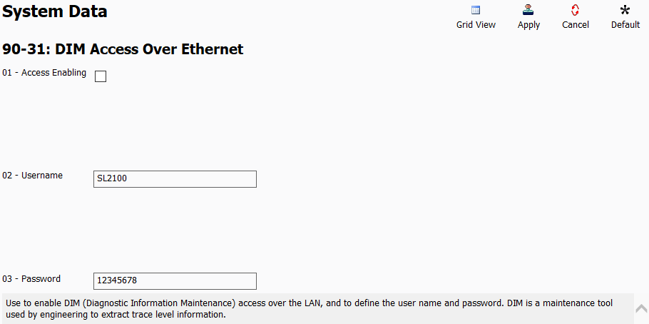
Diagnostic Information Maintenance
In form 90-31 we find the username and password for the diagnostic information maintenance (DIM). By default it is not enabled. It is a maintenance tool that is supposed to be used by engineering.
NEC SL2100 DIM Access
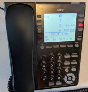
NEC IP Phone Default Password
The default username is ADMIN and the password is 6633222. This password works for the SL2100 IP phones, and may be applicable to other NEC IP phones like the type used on SV8100 and SV9100 systems.
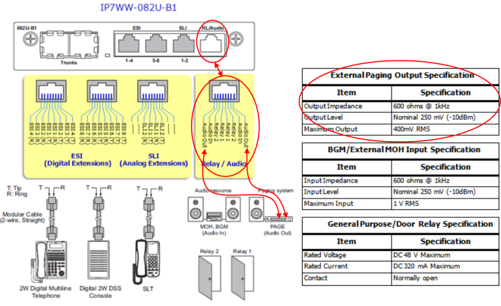
In this tutorial I cover the physical wiring for external paging from an NEC SL2100 as well as basic programming so you can press a button or enter a code on your phone to page to that zone.
Wiring For External Paging
NEC SL2100 paging wiring
In the picture above I have circled the important sections needed to get paging wired up from a standard NEC SL2100 8 port digital, 2 port analog card. Each RL/Audio port can connect to an external paging device, with up to three programmable in the system. So if you had a zone for the overhead paging in the office and a zone for overhead paging in the warehouse, you could use two of these cards and program the ports separately for those zones. For this example I will stick to one.
Note the output specification I circled on the right side of the picture. The NEC SL2100 has a standard 600 ohm output for the paging, which will connect to most paging interfaces over the “Tel” port, and it will also connect directly to many amplifiers such as a Bogen TPU 100 or 250 over the “Tel” posts as these match the impedance of the SL2100 paging port.
If you use a standard SL2100 install cable pay attention to the plug you insert into the RL/Audio port. Take a look at the wiring with the clip facing down and make note of the color of the wires on the outside of the clip (see the picture above). These wires are what you will use to connect to your paging interface, or directly to the amplifier.
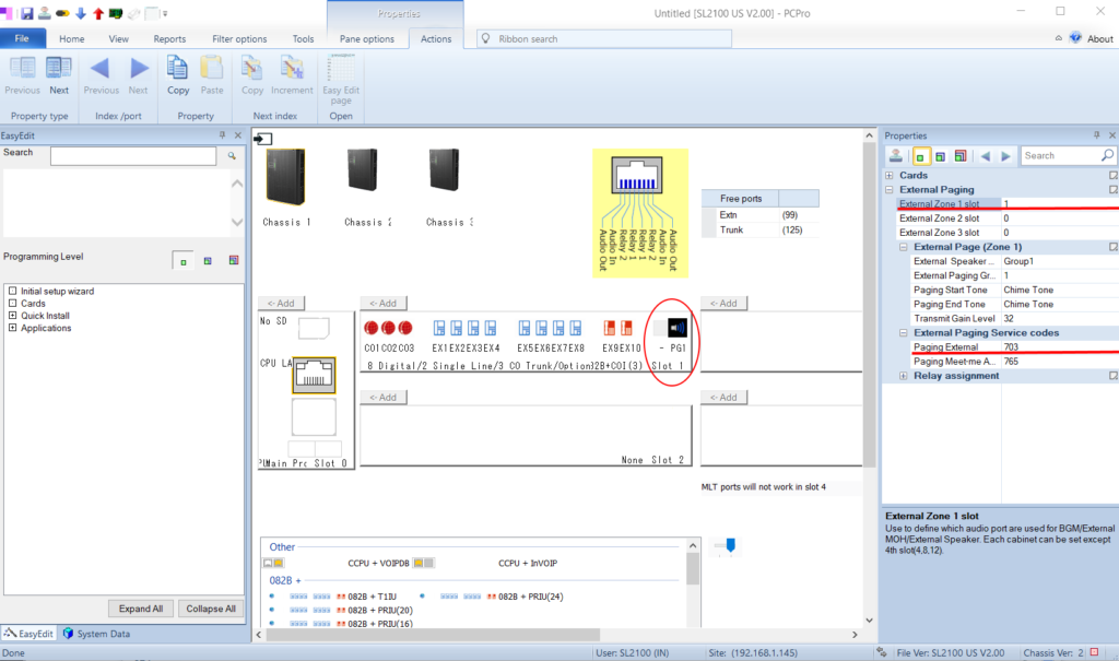
Programming the external paging
Once the physical connection is made we can move onto programming. Again, I’m keeping this simple with one external page zone, but the SL2100 can be programmed for up to three external zones, a lot of internal zones, and you can mix internal and external zones together if needed.
NEC SL2100 External Paging Programming
Open the PC Pro program, connect to your system and download all of the data from it. Once that is complete we are going to select the Chassis View selection near the top of PC Pro (Chassis View is next to Cards). Once you are in Chassis View you should see about the same as the picture above, but probably without the PG1 selection that I have circled if the system was never programmed with external paging. Right click on the right side blank area of Slot 1 (see the picture above) and then left click PG1 to assign this port as Page Group 1.
Once that is done the system should fill in the rest on the right hand side for you, including External Zone 1 Slot and the External Speaker Name. It will also show you the Paging External service code. From here you can change the name of the speaker group if needed, like naming this group “Office” or “Warehouse” if you were going to have multiple speaker groups. You can also change the start and end tones and change the transmit gain level. I recommend leaving the level alone as you should be changing the volume from the amplifier, not from the phone system. Don’t forget to hit the Apply stamp icon just below the word Properties, then upload the changes to the system!
Now you should be able to just dial the paging external service code (in this example and in most default systems it will be 703), then the display will show “Zone”, dial 1 and you should hear the start tone, then you can speak, and when you hang up the system will play the end tone. This is when you can adjust your “Tel” volume from your amplifier if needed.
Buttons to directly page to this zone can also easily be added to phones now. In PC Pro from the EasyEdit tab select Quick Install, Extensions, then Function Key Template. Now go to the phone you want the button added to. On the left where the button types are shown scroll down to External Group Paging and click on it. You should now see choices of three zones. Choose the zone you want (in this example we only programmed 1) and drag that button to the button you want programmed on the phone and left click to drop the programmed button down on the phone. You should now see “ExPAGE GRP 1” on the button, and you can actually click that text and change it if you want, though unless they have IP phones with self labeling keys users wont see that text. Do this to every phone that needs the paging key, then apply the changes and upload them to the system.Pressing that key will now directly page to external zone 1.
The following steps are for an SL2100 without a VIOP daughter board. They allow you to use the 8 VOIP ports that come with the system to connect IP phones like the IP7WW-8IPLD-C1 shown below. Update – as of SL2100 firmware version 4 you can use up to 16 built in VoIP ports without a daughter board – requires licensing for additional 8 ports.
NEC SL2100 IP Phone Programming
I could not find one definitive source on setting up IP phones with a new system using just the built in VOIP ports so I thought I would detail my steps to help you out. I’m not going to outline starting with a boxed system. I’m going to assume you have the videos published by NEC for setting up a new system into a default state, then accessing it with PC Pro and setting up an initial IP address on your network. Also assumed are a preexisting network with a DHCP server on the subnet you will be using.
VOIP Daughter Board Programming
Updated!
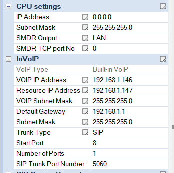
NEC SL2100 CPU Settings
This is where I had issues as I could not find exactly how it should be configured. Here is what I have set up. I am using PC Pro and utilizing the very handy EasyEdit tab. Under Quick Install, CPU Settings, CPU IP address set to 0.0.0.0 (it will be replaced by the VOIP card). Configure default gateway and subnet mask to what suits your network. Then fill in VOIP IP address for your network. Set the VOIP Subnet for your network as well.
From there go down one step in EasyEdit to VOIP Resource IP Address and program the VOIPDB DSP IP Address as an IP one higher than the VOIP IP. Following the above example I put the DSP IP as 192.168.1.147. I left the RTP port at the default 10020. Make sure to upload all changes then reset the system for the changes to take effect.
Now when you connect to the system you will use the programmed VOIP IP rather than the old CPU IP address that you just zeroed out.
IP Phone Programming
Once more I assume you are using the default system and just want to get IP phones up and running without a ton of work. So this method utilizes the Plug and Play steps NEC outlines. When the phone comes online after programming it will grab an open IP extension and “just work”.
Plug the IP phone into the network via a POE switch port and once it is online it should cycle to a SIP Server Not Found error. From there press the following button sequence, HOLD – Transfer – * – #. The screen should show User Name: ADMIN now. Press the down arrow to move to the Password field and input 6633222 and then press the Okay softkey. Press the down arrow on the next screen to go to SIP Settings and press the circular enter button above the down button to enter the page. Press the down arrow again and then enter on Server Address & URI. Now select 1st Server Address. Finally we reach pay dirt! This is where we put in the IP we entered for the VIOP IP, which in my example is 192.168.1.146.
Back out of those settings by pressing the exit softkey and two options below Server Address & URI is SIP Server Port. Enter into 1st Server Port and make sure you have 5080 in this field, unless for some reason you changed it in form 10-16-59. Press okay once you have the port entered.
Once you have these settings input press the exit softkey until you can save your settings on the final page.
The phone will now reboot and if everything was done correctly it will just grab that next open IP phone extension. From there you can program the phone like normal. You can have up to 8 SIP phones programmed like this without purchasing an actual VOIP daughter board and additional IP licenses.
This works for the SL2100 and should also work for the SV8100 and SV9100, but your mileage may vary.
Virtual extensions in the NEC world are very useful. For basic incoming calls you can point a trunk to a ring group. But for more advanced call routing we can set up a virtual extension for added flexibility. You can configure the call to ring an initial group of phones, then add a second group, then go to a mailbox for that virtual extension.
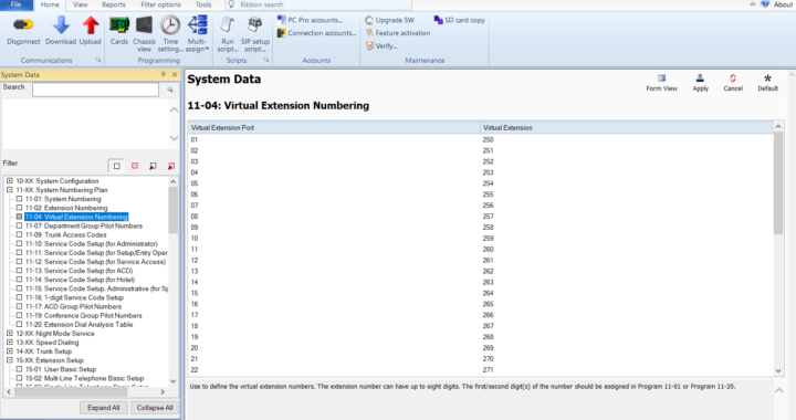
Form 11-04 – Assign the virtual extension. Default systems should have extension numbers already assigned.
Form 15-01 – From the ICM Extension drop down find your virtual extension number and assign the name you want to it. For example “Sales Incoming” or “Service Group”. Don’t forget to click apply after any changes made!
Form 15-07 – Add the key to the a button on the phones you need it to ring at. Sometimes you don’t need the key visible, so you can choose the last function key to assign the virtual, but maybe you do want the key visible to the user, so assign it to a key they can see. To assign a virtual in the SL2100 in the Function field drop down select *3 Virtual Extension Key, then a pop-up should appear where you can use the drop down to choose the virtual extension you are assigning. After you click okay be sure to hit the apply key. Do this for every extension you want to ring.
Form 15-09 – This is where you find the extensions you programmed the virtual extension key on and choose what mode they will ring on. For instance, hit the drop down for the extension and find the one you programmed the key on. After that find the function key you programmed that virtual on (it’s good to have all this in writing before starting). Then just check the box for all the modes so they virtual extension key will ring in whatever mode the system is in. Do these steps for all the extensions you added virtual extension keys to. Keep in mind even if an extension has a virtual key that will delay ring it needs to have a check mark in 15-09, or it wont delay ring at all. So if an extension in 15-09 is set to ring but doesn’t have a check mark in 15-11, it will ring right away, but if the extension has the check mark in 15-09 and 15-11, it will delay ring.
Form 15-11 – This is where you now separate the extensions that ring with that virtual first vs the extensions that will delay ring. Like the step before find the extensions that need to delay ring and then find the virtual extension function key for it and choose all the modes. Now when that virtual is called it will only ring those extension after the timer in 20-04 has run out.
Form 24-09 – Now you will need to find that virtual extension and set it to forward to voicemail. After it has rang the initial set of extensions, then added the delay ring extensions it will go to its own mailbox. On my system InMail is extension 3999, so for Call Forwarding Type I selected Call Forward when No Answer, then put 3999 in all of the remaining fields. If you instead wanted calls to this virtual to go directly to the voicemail for it, you would set the call forward type to Call Forward All. That makes the virtual a front end auto attendant instead of ringing extensions before going to voicemail.
Form 47-02 – I recommend choosing grid view for this form. This way you can find an unused mailbox number. Once you have done that set the type to Personal and the Mailbox Number to your virtual extension. Now you can set up that mailbox with a personalized recording that fits the line that was called. For example you could say “Thanks for calling ABC sales, please leave your name and number and we will call you back as soon as possible”. You could set up the virtual as a group mailbox with mail box type Routing and set up a dial action table instead of just having the unanswered call dump into a voicemail.
Form 15-07 – Now go back to the function key assignment so we can add the new mailbox key to users who will need to monitor it. Choose your extension and a function key. This time make sure it is a visible key to the user. For the key type select InMail Voice Mail access. In the next popup select the virtual extension.
Once all that is done you can point your incoming trunks or DIDs to the new virtual extension. Don’t forget to upload all your changes to your live system.